


What is a relay?
A relay
is essentially a switch that is operated electrically rather than
mechanically. Although there are various relay designs, the ones most
commonly found in low voltage auto and marine applications are
electro-mechanical relays that work by activating an electromagnet to
pull a set of contacts to make or break a circuit. These are used
extensively throughout vehicle electrical systems.
Why might I want to use a relay?
There are several reasons why you might want or need to use a relay:
- Switching a high current circuit using a lower current circuit
This
is the most common reason and useful where an in-line switch or the
existing circuit does not have the capacity to handle the current
required. For example, if you wanted to fit some high power work lights
that come on with the headlights but there is a risk that they would
exceed the capacity of the existing loom.
- Cost saving
High
current capacity wiring and switches cost more than lower current
capacity versions, so by using relays the requirement for the more
expensive components is minimised.
- Activating more than one circuit from a single input
You
can use a single input from one part of an electrical system (e.g.
central locking output, manual switch etc.) to activate one or more
relays that then complete one or more other circuits and so carry out
multiple functions from one input signal.
- Carrying out logic functions
Electromagnetic
relays can be put to some quite clever (and complex) applications when
linked up to perform logical operations based on certain inputs (for
example, latching a +12V output on and off from a momentary input, flashing alternative left and right lights etc.). Although these logical functions have now been superseded by electronic modules
for OEM designs, it can still be useful, fun and often more cost
effective to use relays to perform them for some after-market projects
(particularly where you have a bespoke application).
Note:
In this article we are going to focus on ISO mini or 'standard' relays
which have a 1" cube body and are the most commonly used in vehicle
electrical systems.
Construction and operation
Inside a relay
This is what the inside of an ISO mini relay looks like:


A
copper coil around an iron core (the electromagnet) is held in a frame
or 'yoke' from which an armature is hinged. One end of the armature is
connected to a tension spring which pulls the other end of the armature
up. This is the relay in its de-energised state or 'at rest' with no
voltage applied. The braided bonding strap
provides a good electrical
connection between the armature and yolk, rather than relying on
contact
between the armature pivot point alone. The coil and contact (or
contacts) are then connected to various terminals on the outside of the
relay body.
How they work
When
the coil is supplied with voltage a magnetic field is generated around
it which pulls the hinged armature down onto the contact. This completes
the 'high' current circuit between the terminals and the relay is said
to be energised. When voltage is removed from the coil terminal the
spring pulls the armature back into it's 'at rest' position and breaks
the circuit between the terminals. So by applying or removing power to
the coil (the low current circuit) we switch the high current circuit on
or off.
Note: It is important to understand that the coil
circuit and the current-carrying (or switched) circuit are electrically
isolated from one another within the relay. The coil circuit simply
switches the high current circuit on.
The following simplified circuit diagram is often used to easily understand how a relay operates:

Relay terminology
The ISO mini relay we have looked at above has 4 pins (or terminals) on the body and is referred to as a make & break relay
because there is one high current circuit and a contact that is either
open or closed depending upon whether the relay is at rest or energised.
If the contact is broken with the relay at rest then the relay is
referred to as Normally Open (NO) and if the contact is closed with the relay at rest then the relay is referred to as Normally Closed (NC). Normally Open relays are the more common type.
ISO
mini relays with two circuits, one of which is closed when the relay is
at rest and the other which is closed when the relay is energised, have
5 pins on the body and are referred to as changeover relays. These have two contacts connected to a common terminal.
Make
& break relays are also known as Single Pole Single Throw (SPST)
and changeover relays as Single Pole Double Throw (SPDT). This is based
on standard switch terminology. There are other contact configurations
discussed below but make & break and changeover relays are the most
commonly used.
Terminal numbering convention
The terminal numberings found on a relay body are taken from DIN 72552 which
is a German automotive industry standard that has been widely adopted
and allocates a numeric code to various types of electrical terminals
found in vehicles. The terminals on the outside of a 4 or 5 pin mini
relay are marked with numbers as shown below:

Terminal/Pin number | Connection |
| 85 | Coil |
| 86 | Coil |
| 87 | Normally Open (NO) |
| 87a | Normally Closed (NC) - not present on 4 pin relays |
| 30 | Common connection to NO & NC terminals |
According
to DIN 72552 the coil should be fed with +12V to terminal 86 and
grounded via terminal 85, however in practice it makes no difference
which way around they are wired, unless you are using a relay with an
integrated diode (see more info on diodes below).
Tip: you
can use a changeover relay in place of a make & break relay by just
leaving either the NO or NC terminal disconnected (depending on whether
you want the circuit to be made or broken when you energise the relay).
Terminal layouts
The
automotive ISO mini relays we have been looking at above are typically
available in two types of pin layout designated Type A and Type B
layouts. These layouts are shown on the two 5-pin relays below (pin 87a
not present on 4 pin relays):
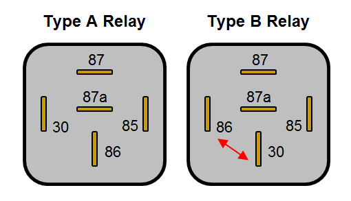
You
will notice that on the Type B layout pins 86 and 30 are swapped over
compared with the Type A layout. The Type B layout is arguably easier to
work with as the connected terminals are in-line, making the wiring
easier to visualise. If you need to replace a relay make sure you use
one with the same terminal layout as it is easy to overlook if you're
not aware of the difference.
Terminal sizes
The
terminal widths used on 4 and 5 pin relays are almost always 6.3mm
wide, however some more specialist relays can have terminal widths of
2.8mm, 4.8mm and 9.5mm. The 9.5mm wide terminals tend to be used for
higher power applications (such as for starter motor solenoid
activation) and the smaller terminals tend to be used for electronics
signalling where only very low currents are required. All widths will
be compatible with the standard female blade crimp terminals of the corresponding sizes.
Relay body markings
Relays
can look very similar from the outside so they normally have the
circuit schematic, voltage rating, current rating and terminal numbers
marked on the body to identify them.
- Circuit schematic
This shows the basic internal circuits (including any diodes, resistors etc.) and terminal layout to assist wiring.
- Voltage rating
The
operating voltage of the coil and high current circuits. Typically 12V
for passenger vehicles and small craft but also available in 6V for
older vehicles and 24V for commercial applications (both auto and
marine).
- Current rating
This
is the current carrying capacity of the high current circuit(s) and is
normally between 25A and 40A, however it is sometimes shown as a dual
rating on changeover relays e.g. 30/40A. In the case of dual ratings the
normally closed circuit is the lower of the two, so 30A/40A, NC/NO for
the example given. The current draw of the coil is not normally shown
but is typically 150-200 mA with a corresponding coil resistance of
around 80-60 W.
Tip: Knowing the coil resistance is useful when testing the relay for a fault with a multi-meter. A very high resistance or open circuit reading can indicate a damaged coil.
- Terminal numbering
The
numbers 85, 86, 30, 87 & 87a (or other numbers for different relay
configurations) are normally moulded into the plastic next to each pin
and also shown on the circuit schematic.
Relay configurations and types
In
addition to the basic make & break and changeover configurations
above, ISO relays are available in a number of other common
configurations which are described in the table below:
| Configuration | Circuit schematic * | Description |
| Make & break relay | 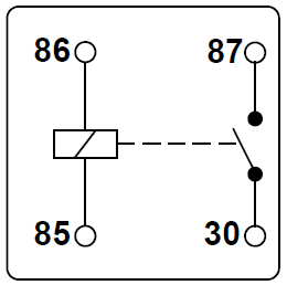 | The most simple form of relay. The circuit between terminals 30 and 87 is made on energisation of the relay and broken on de-energisation, known as NO (or vice-versa for a NC relay). |
| Changeover relay | 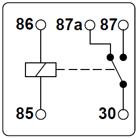 | Two circuits (terminals 87 and 87a ) have a common terminal (30). When the relay is at rest 87a is connected to 30, and when the relay is energised 87 becomes connected to 30 (but never both at the same time). |
| Relay with double output | 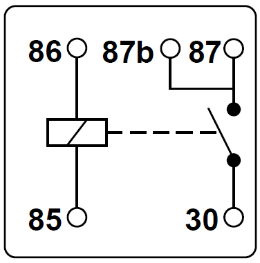 | Terminal 87 is linked to pin number 87b, giving double outputs from the single NO contact. |
Relay with dual contacts | 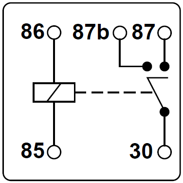 | The armature contacts both terminal 87 and (in this case) 87b at the same time when the coil is energised, creating a dual NO output |
Relay with integrated fuse | 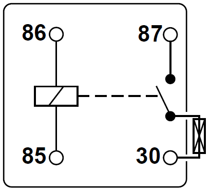 | A blade or ceramic fuse is connected between terminal 30 and the NO contact, providing built-in protection for the high current circuit. The fuse is normally mounted in a holder moulded as part of the relay body so it can be replaced if it blows. |
Relay with diode across the coil | 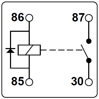 | When voltage is removed from terminals 85/86 and the coil is de-energised, the magnetic field that has been created around the coil collapses rapidly. This collapse causes a voltage across the coil in the opposite direction to the voltage that created it (+12V), and since the collapse is so rapid the voltages generated can be in the order of several hundred volts (although very low current). These high voltages can damage sensitive electronic devices upstream of the +12V coil supply side, such as control modules in alarm systems, and since it's common to take low current alarm output signals to energise relay coils, equipment damage is a real risk. Using a relay with a diode across the coil can prevent this damage by absorbing the high voltage spikes and dissipating them within the coil/diode circuit (this is known as a blocking or quenching diode). The diode will always be installed in the relay with the stripe on the diode body facing towards terminal 86 (reverse biased) and it is important that +12V is connected this terminal, not 85 (as per the DIN standard) or the diode could be damaged. |
Relay with resistor across the coil | 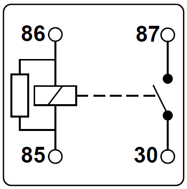 | A high value resistor performs a similar function to that of the diode in the previous configuration by absorbing the high voltage spikes created by the collapsed magnetic field on de-energisation of the coil. The disadvantage of a resistor is that it allows a small current to flow in normal operation of the relay (unlike a diode) and is not quite as effective as a diode in suppressing voltage spikes, but it is less susceptible to accidental damage because resistors are not sensitive to polarity (i.e. it doesn't matter whether +12V is connected to terminal 85 or 86). |
* All schematics shown with the relay at rest (de-energised)Micro relays
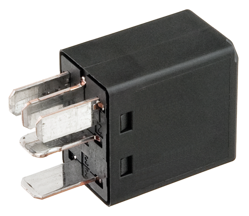
ISO micro relays
are, as the name suggests, smaller than ISO mini relays and designed
for use in applications where space is at a premium. They are
rectangular in section and narrower than a mini relay with a slightly
different pin layout, and are typically available in 'make and break'
and 'changeover' configurations, with and without suppression diodes.
In addition, the terminal numbering is different, using 1, 2, 3, 4 & 5 instead of 30, 85, 86, 87 & 87a.
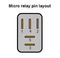 |  |
Terminal/Pin number and size | Connection |
| 1 - 4.8mm | Coil |
| 2 - 4.8mm | Coil |
| 3 - 6.3mm | Common connection to NO & NC terminals |
| 4 - 4.8mm | Normally Closed (NC) - not present on 4 pin relays |
| 5 - 6.3mm | Normally Open (NO) |
More complex relay types
There
are other relay designs that are used for some more complex
applications in vehicle systems. They are still based upon the principle
of switching higher current circuits using smaller current circuits but
often combine this with electronics to perform special functions: Some
examples are:
- Glow plug relays
- provide power to the glow plugs in a diesel engine for a set amount
of time using an ignition switch position or other input to energise the
relay. - Fuel injection relays
- provide power to the electrically activated fuel injectors in a
petrol engine for varying amounts of time based on signals from the
vehicle Engine Control Unit (ECU). - Timer relays - for example in a circuit for a heated rear window, where the relay needs to be energised for a few minutes before turning off.
- Flasher relays/units
- used for operating indicators and hazard warning lights and employ
electronics to control the timing of the contact opening and closing
rather than a traditional bi-metallic strip.
These more
complex relays can have up to 9 pins of various sizes. This increase in
the number of terminals over the standard 4 or 5 in more simple relays
is often necessary because additional connections can be required for
the in-built electronics (e.g. inputs from sensors or the ECU and
outputs to indicator lights or the ECU).
Example relay wiring schemes
The following diagrams show some common relay wiring schemes that use 4 pin ISO mini relays.
| 1. Adding driving lights that come on with the headlight main beam | |
This simple circuit uses the power feed to the headlight main beam bulb as the trigger to energise a relay. The high current circuit in this relay feeds power to the driving light bulb, so every time headlight main beam is selected, the coil is energised and the driving lights operate. Note: It is important that the new power feed to the driving lights is fused appropriately (see our Knowledge Centre fusing guide) | |
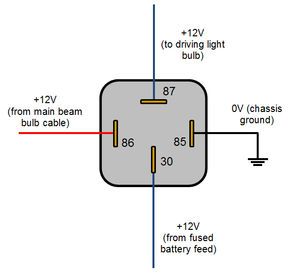 | Terminal 86 - Connect to the +12v cable feeding power to the headlight main beam bulb (achieved by making a splice in the original loom). Terminal 85 - Connect to a suitable earthing point on the vehicle chassis. Terminal 30 - Connect to a +12V feed from the battery. Terminal 87 - Connect to the +12V terminal of the driving light bulb or driving light loom. Tip: It is a good idea to use a separate relay for the left and right hand driving lights and have them switched independently from the left and right hand main beams. This way, if a relay on one side fails the driving light on the other side will still work. |
| 2. Adding a buzzer that warns when you've left your headlights on | |
This circuit is designed to alert you that you've left your lights on by activating a buzzer when you open the driver's door. The coil of the relay is fed from the headlight power cable so that it will only be supplied with +12V when the headlight switch is on. If the headlights are on and the driver's door is opened, the door switch will complete the coil circuit which will complete the 'high' current circuit to the warning buzzer. Notice that In this case the current draw of the alarm/buzzer will be very low so it can be fed from the same +12V supply that is used for the coil. A warning light could easily be added in parallel to, or used instead of, the buzzer. | |
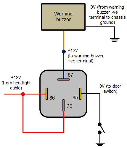 | Terminal 86 - Connect to the +12v power feed to the headlights (achieved by making a splice in the original loom). Also connects in parallel to terminal 30. Terminal 85 - Connect to the driver's side door switch. Terminal 30 - Connected from terminal 86. Terminal 87 - Connect to the +12V terminal of a warning buzzer and then connect the warning buzzer -ve terminal to ground. |
| 3. Adding a hidden switch that must be pressed to enable the vehicle to be started | |
This is a clever little circuit involving two relays and a momentary switch and is more a of a 'logic' circuit than one used to switch a high current with a low current. Once the ignition key is in the IGN position, you press and release the momentary switch and then turn the key to the START position and fire the engine as normal. The button press momentarily energises the coil of Relay 1 which allows +12V out of terminal 87 and into terminal 86. This has the effect of keeping the coil energised after the button is released (note that whilst the button is pressed there is 0V between terminals 86 and 87). Terminal 87 also sends power to the coil of Relay 2 which enables the starter motor solenoid connection, ready for when the key is turned to the START position. When the ignition is turned off the power to the coil of Relay 1 is cut which cuts the power to the coil in Relay 2 and breaks the starter motor solenoid circuit, so the engine cannot be started again without going through the above routine. The momentary switch can be mounted out of sight and acts a simple starter inhibit security device. | |
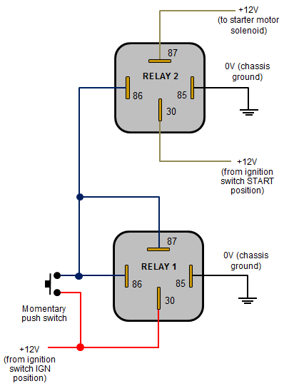 | RELAY 1 Terminal 86 - From one side of momentary switch. Terminal 85 - Connect to a suitable earthing point on the vehicle chassis. Terminal 30 - From +12V ignition switch IGN position. This supply also feeds the other side of the momentary switch. Terminal 87 - To terminal 86 and Relay 2 terminal 86. RELAY 2 Terminal 86 - From Relay 1 terminal 86. Terminal 85 - Connect to a suitable earthing point on the vehicle chassis. Terminal 30 - From +12V ignition switch START position Terminal 87 - To starter motor solenoid. |